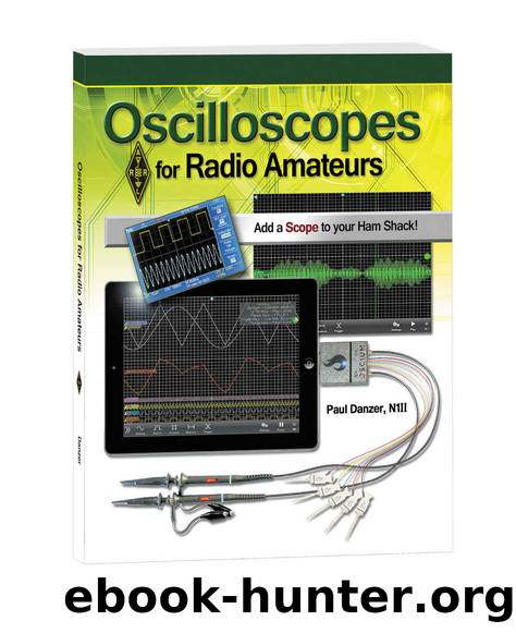
Oscilloscopes for Radio Amateurs by Paul Danzer (N1II)

Author:Paul Danzer (N1II) [Danzer (N1II), Paul]
Language: eng
Format: mobi
Publisher: ARRL, the national association for Amateur Radio
Published: 2015-04-14T07:00:00+00:00
Chapter 7
Letâs Put a Scope to Work
Oscilloscopes are generally used for one of three types of measurements: amplitude (voltage), duration or time (frequency), and calculations. Most older scopes did not have the ability to do calculations, but as discussed in preceding chapters, as long as you have information in digital form and are using a digital processor (in other words a small computer), the oscilloscope can do a variety of calculations.
Amplitude Measurements
When most people think of using an oscilloscope, they envision a screen with a plot of the amplitude or voltage of a signal on the vertical axis of a screen, along with time on the horizontal axis. To make this primary plot on the display, there are several steps you have to take. It is very possible to overlook one of these steps, in which case the displayed waveform may mislead you and not represent the true picture of the signal.
First pick a voltage scale, and if there is a variable scale control, make sure the voltage scale selection switch is in the calibrated position. Looking at Figure 7.1 you can see scale selection switches for channel 1 and channel 2. Notice that the center knob (labeled VAR) for channel 1 is in the full clockwise position, corresponding to the calibration position on the panel. The VAR knob for channel 2 is not in the same position, so as a result the voltage scale selected for channel 1 is correct but the scale selected for channel 2 is incorrect. It is very easy and very common to overlook checking this setting.
Check your probe compensation. Compensation, as noted in a prior chapter, only holds for the X10 setting on the probe switch. If you are looking primarily at sine waves and RF, it is doubtful that (except for extreme maladjustment of the compensation screw) this adjustment will make much of a difference. Digital signals are a different story â just look at Figure 7.2! With compensation maladjustment, square waves, pulses, sawtooth and other linear waveforms may be shown far from their true waveshape.
Download
This site does not store any files on its server. We only index and link to content provided by other sites. Please contact the content providers to delete copyright contents if any and email us, we'll remove relevant links or contents immediately.
| Electron Microscopes & Microscopy | Experiments & Projects |
| Measurement | Microscopes & Microsocopy |
| Scientific Instruments | Telescopes |
| Time | Methodology & Statistics |
Thing Explainer by Randall Munroe(3337)
The Elements by Theodore Gray(2448)
Make by Mike Westerfield(1974)
The Meaning of it All by Richard Feynman(1915)
Science Experiments You Can Eat by Vicki Cobb(1453)
Every Tool's a Hammer by Adam Savage(1446)
The Perfectionists by Sara Shepard(1433)
Raspberry Pi Electronics Projects for the Evil Genius (Tab) by Norris Donald & Norris Donald(1388)
Hands-On Genetic Algorithms with Python by Eyal Wirsansky (2020) by Unknown(1369)
Martin Gardner's Science Magic by Martin Gardner(1358)
The Perfectionists by Simon Winchester(1272)
Elephants on Acid: And Other Bizarre Experiments by Alex Boese(1255)
Synchrotron Light Sources and Free-Electron Lasers by Eberhard J. Jaeschke Shaukat Khan Jochen R. Schneider & Jerome B. Hastings(1238)
Elephants on Acid by Boese Alex(1237)
Handbook of Modern Sensors by Jacob Fraden(1230)
Tesla by Carlson W. Bernard(1187)
The Science of Food by Marty Jopson(1168)
The Meaning Of It All by Richard P. Feynman(1129)
125 Physics Projects for the Evil Genius by Silver Jerry(1120)
